Sort articles by: Date | Most Rates | Most Views | Comments | Alphabet
Article info
  • Views:
  • Author: vipsoft
  • Date: 20-05-2010, 17:49
20-05-2010, 17:49

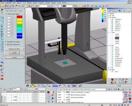
Metrolog XG v8.002

Category: CAD/CAM CNC

Metrolog XG v8.002


Points Cloud *

Full Metrolog optimization to be able to process millions of points.
New database points cloud tab page.
Possibility to acquire clouds in manual (using arms or laser) or automatic modes (using arms, T-Scan, CMMs).
Three new alignment creation instructions point cloud oriented:
Quick-fit
Best-fit
Fit on retrieved features
Improvement of feature retrieve functionality (circle, plane, flush and gap...).
New "Surface Mapping feature for points cloud analysis on the complete CAD or on a part of the CAD. Ability to generate automatically a color mapping associated to this feature.
New Flush & Gap feature.
Points cloud meshing with optional smoothing included.
Advanced points cloud filtering functionalities.
AC, PSL, STL, MTL import / export file formats.
Specific toolbar for point cloud 3D view visualization.
Features
Better consistency between Surface Point and Geometrical Point : same display, same result window, same automatic measurement methods, same print report, same way to define coordinates.
All feature construction fields can be set with calculated values.
Ability to define circle on a cone surface with automatic diameter adjustment.
Possibility to use CAD curves or sophisticated CAD projections to define surface points or geometrical points.
New construction of a geometrical point : offset a point along a direction and a distance.
Best-fit feature construction based on other features probing points.
Construction of line based on other feature direction (main axis or normal).
Automatic inner / outer property recognition in the feature definition dialogs, according to the click or the CAD.
It is now possible to evaluate a circularity on a cone (ISO 1101:2004).
Feature naming rule improvement.
Warning during definition if the shape does not fit the feature. (if a user try to define a circle on elliptic shape).
Single and total runout improvement
Trackers and Arms functionalities
Possibility to use a Metrologic Bundle available to all types of trackers and arms. *
Sphere and circle features can now be used as orientation points.
Improvements in the Build & Inspect: *
a control points prefix name and a family name can be set,
possibility to compare axial feature to cylinder parallel or not to the current alignment axes,
possibility to compare cylinders and cones features to reference shapes.
Ability to combine automatic mode and manual probing.
Support point temperature compensation for Leica, API, Faro tracker. *
Import / Export
Support of the GSURF statement in the DMO import. *
Possibility to import basic point files in working sessions (position, position with normal, point name and position, etc.).
Features (including 3D features shape) can be exported as IGES file.
GM2 program engine
Improvements in path display (ability to display path on part program selection or on all program, and possibility to display only probing points).
Direct jump from active feature to its definition instruction in a part program.
New Find and Replace dialog.
New program import format: DAT.
Improvements in the PNT program converter:
define and/or measurement instructions,
automatic normal calculation by projection on CAD,
selection of the features of the file.

Improvement of the POLAR coordinates management :
teach probing points in the coordinates system of the definition feature,
teach constructions in the coordinates system based on the coordinates system of the features,
support polar coordinates in the Convert Hit Points dialog.
New security position management instructions.


In off-line, possibility to force a part program to be run in automatic mode.
Manual probing assistant can now be based on probing points during a part program execution.

DMIS program engine *

New dialog to generate easily OUTPUT instructions.


Approach and Retract distances automatically adapted to feature size. And these instructions are now learned in the part program.
Automatic recovery of head position and execution mode in a DMIS part program.
Improvements in the PNT program converter:
define and/or measurement instructions,
automatic normal calculation by projection on CAD,
selection of the features of the file.
Improvement of the POLAR coordinates management :
teach probing points in the coordinates system of the definition feature,
teach constructions in the coordinates system based on the coordinates system of the features,
support polar coordinates in the Convert Hit Points dialog.
Possibility to run an external program via the ScriptEngine.
Ability to set a prefix feature name in the Convert Hit Points to Geometrical Points dialog.
Ability to update feature/alignment databases when editing DMIS alignment statements.
CAD

CAD entities orientation visualization in the 3D view.
Possibility to reverse the entity orientation.
When defining a geometrical feature from a CAD entity, automatic inner / outer property initialization based on the surface orientation.
Possibility to create a CAD surface by extension with one click on a circle.
Catia V5 R17 supported. *
Automatic CAD surfaces re-orientation with one click.
3D View
Ability to show / hide alignment representation in 3D view for current or CAD alignments.
It is now possible to modify the alignments axes sizes.
New statistic histogram column that can be added in stickers.
New detailed 3D view for form tolerances (flatness, straightness, circularity and cylindricity).
The feature names are now displayed in transparency in the 3D view.
Stickers: feature icon depends of the font size.
Probes *
Faster continuous probes qualification process based on simple points calibration.
Optimized SP600 and SP25 probes calibration.
Support of "L" continuous probes calibration (manual and automatic).
CMM interfaces *
Faro Track Arm.
Perceptron optical sensor on ME5007, ME5008 and CimCore Infinite arms.
Kreon optical sensor available on ME5007 and ME5008.
Leica T-Scan.
Faro Scan Arm.
Reminder: Possible setup with opticals sensors:
Sensors
T-Scan Perceptron Kreon Datapixel Metris ScanArm
Interfaces Leica
LTD Series X
CimCore
Infinite X X
Faro
Titanium/Platinium X X
ME5007
ME5008 X X Next Patch Next Patch
Miscellaneous
It is now possible to define the translation values of a geometrical alignment directly by clicking in the 3D view.
Possible to auto-detect CMM parameters in the Setup Assistant.


New possibility to choose between nominal and actual values in calculated values.


New setting to define the delay between continuous mode and standard mode (portable CMM).
When using the Operator mode, the starting program folder is always reinitialized to its right value after a program execution.
Advanced settings panel can be resized.


Metrolog XG v8.002

Tags: feature, program, points, coordinates, automatic, features, define, probing, Possibility, point, based, instructions, Points, Ability, system, cloud, possibility, dialog, alignment, definition

Article info
  • Views:
  • Author: vipsoft
  • Date: 14-09-2010, 10:09
14-09-2010, 10:09

Giben Optisave 5.3

Category: CAD/CAM CNC

Giben Optisave 5.3


The new Windows version of GIBEN OPTISAVE cutting patterns optimising program is based on 32 bit technology and thanks to Windows, represents a simple optimisation tool for the user.

The 32 bit technology definitely helps in reducing working times, thus offering further important advantages:

Mouse and windows user interface control
Cutting pattern overall view with zoom function
No limit in managing quantities of parts with same and different sizes
No limit in board sizes
Production control of more machines in network
Link from and to the optimising program and control of the machine
Simple import & export functions
Simple optimisation control by different parameters lists with windows user interface technology


INFO
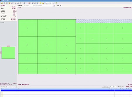
The OPTISAVE control menu is on the left hand side of the screen.
The user enters the operating windows and moves to another just by a mouse click.
The windows user interface technology increases its friendly use, thus allowing the handling of different processes.


The optimisation can be controlled by using different parameters.
The parameters are available to the user divided into groups (trim cuts handling, cycle times, limits)
Simplicity makes OPTISAVE easy to use.
The integrated control of rests/stock and the possibility to optimise optional parts assure brief material storing times, reduction of rests storage with consequent decreasing of stocking value.


All cutting patterns per job are clearly available on the screen.
By a mouse click the user can look through a given cutting pattern or modify it manually.
Zoom function allows further views.
By using Page Up and Page Down keys the user can browse to following cutting pattern and get back to the previous one or can enter the overall view page.
Different analyses can be worked out each job in the form of cutting lists, pile or protection boards list.


The following information is available for each job:
Cut parts and optionals.
Quantity of raw boards used.
Waste, cutting times.
Number of cutting patterns, cycles and unloading stations.
Required cutting time.

IMPORT & EXPORT FUNCTIONS
Our OPTISAVE standard user interface offers the possibility of connection with managing systems (part lists acquisition, cutting data and times feed back) as well as of serial and network link for the control of the panel saw.

Giben Optisave 5.3

Tags: Giben Optisave Serial

Article info
  • Views:
  • Author: vipsoft
  • Date: 20-09-2010, 09:49
20-09-2010, 09:49

Ottimo Perfect Cut 6.30 - 7.33 - 7,70

Category: CAD/CAM CNC

Ottimo Perfect Cut  6.30 - 7.33 - 7,70


Ottimo-Perfect Cut is a cutting optimization software for single blade and angular beam saws with several features such as: materials archive management, pieces archive management, single-job and multi-job (cutting list with pieces of several materials) optimization, expected machining time and costs computation, machine code generation, production reports, panels labeling, 3D simulation.
Ottimo-Perfect Cut is installed in a PC with Windows® O.S. in the factory or in the office, can be connected with an Ethernet network with the administration software and with the Panel saw software interface.
Ottimo-Perfect Cut allows to obtain an optimized sequence of cutting pattern starting from a cutting list, a material list and a machine configuration. By modify the configuration parameters you can obtain the solution as needed, with minimum waste or minimum machining time. Complete production reports are available. Optimized programs can be exported easily to the panel saw. Moreover the optimizer shows report with estimated times and costs and output customized labels for obtained pieces and off-cuts.
* Materials Database (up to 3.000 different sheets)
* Sheets classification for material type
* Grain and trims information for each type of material
* Automatic used sheets unloading and off-cuts recycle
* Pieces Database (up to 10.000 different pieces)
* Simple job programming to optimize cutting lists with panels of the same material.
* Standard parameters can be customized for each job in order to obtain the best result.
* Several sheets and off-cuts formats can be selected to cut pieces
* Production data, waste and machining time are showed to check immediately for result
* Automatic filling of cutting patterns with by using a filling list.
* Report with optimization general statistics (linear meters, surfaces area, volumes, waste, etc...)
* Materials, panels and strips report
* Graphical lay-outs of cutting patterns with pieces and waste dimensioning
* All reports can be saved as PDF files
* The manual editor allows to insert, delete, move and rotate pieces; to insert, delete and move head-cuts
* Details are showed for each selected panel or waste in the pattern.
* The pieces can be inserted from the job list, from the piece archive or as a new piece
* Statistics of the modified pattern are automatically updated
* The multi-job programming allows to optimize cutting lists (up to 10.000 lines of pieces) with panels of several materials.
* The original cutting list is exploded in several simple list with pieces of the same material
* Summary report of the complete job

JOB IMPORT, COSTS, MACHINE CODE GENERATION
* Job import from a formatted text file or from Excel ® (EasyCut or EasyCut Plus required)
* Export of machine programs saved onto floppy disks, local or Ethernet paths
* Export of a list of program with several type of materials (LLT format)
* Export (splitting) of a single job up to three different panel saws
* Estimated machine time and costs
PIECES LABELING
* Labels can be printed every single piece or by book or by stack of pieces.
* Labels can be printed off-line in the windows printer or on-line in the label printer at the saw by automatic sending label data for the pieces
* Labels can be printed for both pieces and off-cuts of the job
* Graphical Label editor with text, barcode, lines, drawings, to customize the label templates
3D SIMULATOR AND PIECES UNLOADING REPORTS
* Virtual machining 3D simulation of the job
* View of expected machining time
* View of the active cutting pattern with information on the machining cycles
* Configuration of dimensional parameters for the pieces unloading process
* Stacks report for each piece
* Chronological report of stacks composition with graphical lay-out
* Report of used pallets with graphical lay-out

Ottimo Perfect Cut  6.30 - 7.33 - 7,70

Tags: Ottimo Perfect Cut, 630, 733, 770, Smarkey, Eutron, Dongle, Download, CNC, pieces, cutting, machining, report, several, waste, material, offcuts, machine, piece, pattern, panels, materials, panel, obtain, label, software, printed, OttimoPerfect, Export

Article info
  • Views:
  • Author: vipsoft
  • Date: 3-10-2010, 21:21
3-10-2010, 21:21

OmniCad

Category: CAD/CAM CNC

OmniCad


CAD Surface modeler
OmniCAD® is a 3D surface modeler CAD integrated with a 2D environment. OmniCAD® is a sophisticated software produced and developed over the years for mould and die designing and for constructing complex 3D models, its main aim being precision problem solving. Its numerous verticals, backed up by power and speed calculation, versatility and precision, make OmniCAD® an essential tool which has today become an absolute reference point in the automotive environment.

The OmniCAD® engine
No efficient verticals or automatisms could be possible without a well designed engine.
OmniCADs verticals are powerful, thanks to a stable, robust and well performing engine, to the point that the most difficult operation seems simple and natural.

Main Functions
Production of all surface types with pass and tangency conditions, creation of blending surfaces with group selection, automatisms to create groups of surfaces bounded to certain circumstances, projection modelling and multiple trimmings on various surfaces. Functions to create surfaces starting from an existing model. Verification function on the surfaces: tangency conditions, convexity etc, functions for approximation and conversion of different types. Functions for a complete 2D drawing.

Functions dedicated to the Sheet-Metal Die and Moulds
Macro-automatisms and commands with finishing functionalities make up a tool able to complete a die design within very competitive time limits. For certain operations that have a significant effect on the speed of project completion (for example the trimming development), OmniCAD® must be the final choice.


Surmod : the module for modification comparisons
Surmod compares two mathematical models underlining the modifications in terms of volume and shape. By using this instrument, the empiric methods commonly used in modification comparisons can be omitted. Even though SURMOD allows some operative freedom, it provides final solutions adopting a scientific approach and reports detailed documentation to certify the analyses carried out

OmniCad

Tags: omnicad full, hardlock,

Article info
  • Views:
  • Author: vipsoft
  • Date: 24-11-2010, 15:56
24-11-2010, 15:56

Aspan Autosoftware CAD/CAM 9.3

Category: CAD/CAM CNC

Aspan Autosoftware CAD/CAM 9.3

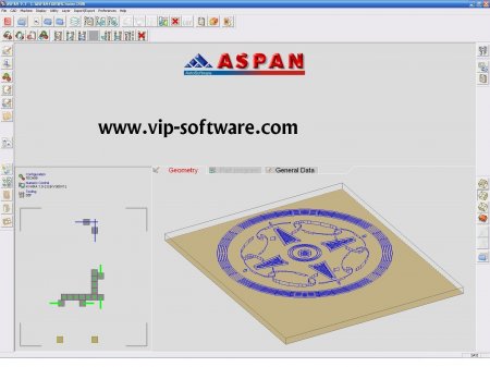
ASPAN is a CAD/CAM application recognized throughout the world as the easier and much user-friendly application in the area of programs for working wood, aluminium, plastics through numerical control machines. It can handle different types of machines and allow, starting from a sigle drawing, to generate part-programs for many machines.

ASPAN enjoys a world-wide reputation as the easiest-to-use software with a user-friendly interface for programming woodworking machinery. Furthermore, the program is very powerful with a hundred high-level commands, functions and options.
Originally created in DOS in 1992, the program has been continuously updated to keep pace with the new operating systems. Performance has been developed and improved with the continuous addition of new commands and functions.
We are proud to say that any of the problems experienced by our customers over the years have been solved by our internal troubleshooting SERVICE (service-disk). We reproduce and solve errors here at AutoSoftware without the need to intervene at customer sites.
ASPAN is an integrated CAD-CAM program. Users draw their production parts quickly and easily in the CAD environment and then transfer these to the CAM environment to prepare the optimized machine programs needed to actually produce the part.
A set of easy to understand commands (e.g. “Draw Holes”, “Draw Grooves”) and automatic routines (e.g. “Assign tools”, “Optimize machining sequence”) make it easy for users to define the machining operations to be performed on the unfinished parts.

The subdivision of the working environments allows the user to be easily guided throughout all development and operation phases:
SUPERVISOR:
The main or Supervisor environment, which appears after the program has started, displays the preview image of the current drawing, on the right, and the list of the current archive along with search and selection options. If the drawing has been processed in the CAM environment, machine efficiency is displayed at the top right of the screen (ratio between empty shifts and real operations). From this environment it is possible to carry out import or edit procedures for machine configuration and tooling and to run all other program environments.
CAD:
This is the drawing environment used to create graphic entities such as various types of hole (e.g. standard, countersunk, in lines, angled, hole barriers, ect.) and routings (e.g. straight grooves, arcs, ellipses, rectangles, points, , ect.). Standard commands (e.g. “Join”, “Rotate”, “Auto-join”) and advanced functions (e.g. “Text”,“Empty area”, “Inclined surfaces”) are used to create the desired drawings.
CAM:
This is the environment where drawings are converted into machine programs by using a series of utilities for operations such as automatically assigning tools and optimizing machining sequences. A series of special commands (e.g. “Inputs/Outputs”, “Multi-machining”) makes it possible to configure the machine program with the exact specifications (e.g. tools, speed, worktable) of the machine currently being used.

In addition to being a very easy – to-use and quick program, ASPAN provides the most advanced user with an efficient internal language, APL (AutoSoftware Programming Language). With APL users can create new CAD and CAM commands to optimize their design procedures.

ASPAN can be linked to a variety of external programs such as “AutoCAD”, “IMOS”, “KDCw”, “Pattern System”,“Cabinet Ware” and “Drill Mate” by using ASC, an AutoSoftware proprietary format, and DXF files. This means that users can prepare designs with their drawing program of choice and then use Aspan functions to generate the machine programs necessary. Linking one program to another is made easy by a series of Aspan utilities such as the “Import CSV file”.
[ top ]
a connection bridge between different machines

ASPAN can handle various machine types and allows the user to generate programs for multiple machines starting out from a single drawing. ASPAN can also reconstruct a drawing starting out from a machine program. This function can be used as a vital link between machines making it possible to pass data from one machine to another (“a connection bridge between different machines”).
Machines from the world’s leading manufacturers such as Morbidelli, SCM, Biesse, Busellato, Anderson, CMS, Homag, Masterwood, Samec, CO.B.A.L.M., Cosmec, Hakkoç and many others are supported by ASPAN.
N.B.: In any case, please contact Autosoftware by providing your machine model and type of CNC equipment used so that we can check your machine's support and assess your particular problems/case.

Machine and tooling configuration is also made easy by an import procedure for configuration data directly from the machine. This operation allows the user to be up and running in a few and simple steps without wasting time with long setting procedures.
[ top ]
additional modules (options)

ASPAN is a modular system (MO.S.T. - Modular Software Tool) suitable to your specific requirements and composed of the following optional modules:
nesting:
optimized filling of an area (panel of any shape) or the machine worktable (on big panels having various dimensions) with pieces of any shape (graphic entities, complete drawings, ASCII files from other environments, macros);
vector:
conversion of bitmap images (BMP), acquired from scanner or other, colour or black&white, in drawings to be used with the program;
doors:
realization of doors using predefined models and user customizable models; models are composed by the front and the back of the door and it is possible to create new models. Of any model available just define the door dimensions to obtain its drawing and all its machinings. If used together with nesting option, it is also possible to optimize the machine worktable (on big panels having various dimensions) with the selected doors and of the desired quantity.
cabinet:
furniture construction using a set of predefined templates that can be customized by the user. A wizard will guide the user through the process of defining the characteristics of cabinet and application of hardware. The procedure will create the drawings of all the panels that compose the cabinet, containing defined machinings, machine programs and labels. The drawings generated by the cabinet module may be modified as needed within the CAD environment of ASPAN. Cabinet module also can be used in combination with the Nesting optional module.
[ top ]
distributed versions

1. PROSPECT
*

just one machine configuration (expandable up to 5);
*

different options available only upon request;
2. PILOT
*

all options included;
*

unlimited number of machine configurations available;


Aspan Autosoftware CAD/CAM 9.3

Article info
  • Views:
  • Author: vipsoft
  • Date: 25-11-2010, 16:01
25-11-2010, 16:01

LEI WIRE CUT

Category: CAD/CAM CNC

LEI WIRE CUT


LEI WIRE CUT

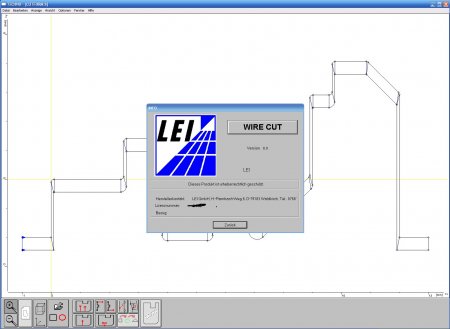
für Drahterodiermaschinen bietet einen komfortablen und leistungsstarken Programmierplatz auf allen Windows-Plattformen:

*
gute Bedienerführung über Ikonen und Funktionsbilder
*
starke technologische Unterstützung
*
leicht zu erlernen
*
selbsttrainierend
*
Sprachen zur Laufzeit: Deutsch, Englisch, Französisch, Italienisch, Spanisch, Tschechisch, (koreanisch)
*

Das mächtige Programmiersystem für die Drahterosion unter Windows

Ikonen und Bildinformationen führen den Benutzer in vier Arbeitsstufen von der Geometrie-Eingabe leicht verständlich zur Erstellung des NC-Satzes.

1.
Sie können im CAD-Teil Geometrien selbst konstruieren oder über Schnittstellen wie DXF einlesen. Sie können Schneidkonturen automatisch oder in Einzelschritten erzeugen.
2.
Im CONIC-Teil können Sie Regelflächen aus Fremdsystemen über die DXF-Schnittstelle einlesen oder aus 2D-Geometrien Regelflächen als Winkelkonik oder 4-Achsen-Konik mit unterer und oberer Kontur erzeugen. Winkelkonik kann in 4-Achsen-Konik konvertiert werden.
3.
Im TECHNO-Teil liegt der Kern des Systems. Hier werden die Flächenkonturen zu Werk-Stücken, denen alle erforderlichen Technologie-Informationen hinzugeführt werden, die für die maschinelle Fertigung erforderlich sind. Mehrere Werkstücke können plaziert und eine Schnittfolge beliebig für die maschinelle Fertigung festgelegt werden.
4.
NC-SIM bietet zum Test ISO-Code und Grafik parallel an.
Mit einer Cassettenrecorderbedienung blättern Sie in der Schnittfolge.
Die integrierte Technologiedatenbank, die zu Ihrer Maschine paßt, können Sie mit eigenen Technologiedaten ergänzen, die zur Laufzeit vom System angeboten und vollautomatiasch in den NC-Code eingesetzt werden.

Zudem gibt es viele Extras im Grundpreis inklusive:

*
aus NC-Files (nc, geo, iso, min) Rückgewinnung der Schneidgeometrie
*
freidefinierbare Postprozessoren etwa für kleine Fräsaufgaben
*
Postprozessor für NC-Code nach DIN 66025
*
erweiterte Winkel-Konik mit Radiusdefinitionen und 4-Achsen-Konik
*
ebene Konturverzerrung für schrägliegende Ebenen
*
Schrägstellen konischer Durchbrüche
*
Konvertieren von Winkelkonik in 4-Achsen-Konik
*
Hinterschnitte entfernen ° unterschiedliche Höhenlage der Werkstücke
*
Zerstörungsschnitt
*
Ausrundung nach minimalen Radien
*
individuelle und automatische Schnittfolgen wie early und late
*
Datenaustausch mit Fremdsystemen (DXF)
*
Zahnräder, Teilräder und Zahnstangen
*
Zahnräder nach DIN-Norm
*
Formdrehstähle
*
Walzenfräser
*
Alle verfügbaren Maschinen eines Herstellers sind im Grundpreis enthalten


LEI WIRE CUT

Tags: können, werden, 4AchsenKonik, Winkelkonik, einlesen, erzeugen, Zahnräder, Extras, inklusive, Regelflächen, Fremdsystemen, Fertigung, Werkstücke, Grundpreis, Laufzeit, NCCode, Schnittfolge, maschinelle, Ikonen, bietet, Hardlock

Article info
  • Views:
  • Author: vipsoft
  • Date: 23-01-2011, 20:53
23-01-2011, 20:53

Orion building design system

Category: CAD/CAM CNC

Orion building design system


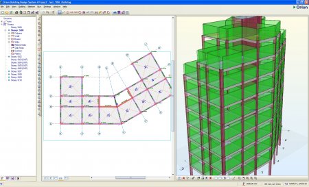
Orion is the ultimate design and detailing software solution for reinforced concrete buildings. Used by thousands of engineers worldwide, Orion is perfect for any sized concrete building project and caters for a wide range of concrete structural systems.

Our software automatically produces detailed calculations, material quantities, structural layout plans, beam and slab elevations and column schedules, all from a single model.


Orion building design system


Article info
  • Views:
  • Author: vipsoft
  • Date: 23-01-2011, 21:12
23-01-2011, 21:12

Polyworks V10

Category: CAD/CAM CNC

Polyworks V10


ROMER is pleased to offer PolyWorks™ software with its ScanShark system.

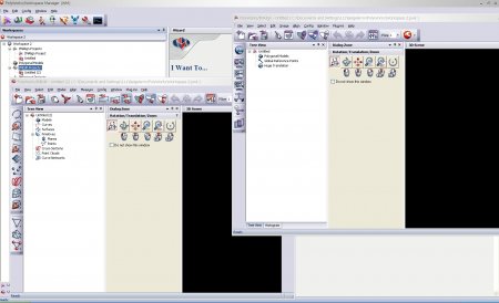
PolyWorks/Inspector™ is a powerful software solution that uses high-density point clouds and contact-probe datasets to control the quality of parts and tools at every phase of your manufacturing process.

Inspector allows users to:

• Use high-density point clouds and contact-probe datasets of digitized prototype parts & assemblies to quickly identify deformations and to fix problems in the earlier stage of the manufacturing process.

• Approve your manufacturing process by fully inspecting your first-assembled products.

• Monitor the production cycle by automatically measuring the wear of tools and quickly detecting any abrupt degradation in product quality.

• Verify the compliance of final manufactured and assembled products through sample check inspection using automated techniques.

PolyWorks/Modeler™ is a comprehensive software solution for creating accurate and smooth polygonal models and NURBS surfaces from high-density point clouds. Preferred by automotive design studios worldwide, PolyWorks/Modeler is the only software solution that has demonstrated the capability of creating class A polygonal models for stringent polygonal manufacturing applications such as 3-axis & 5-axis milling, aerodynamic simulation, and digital review. PolyWorks/Modeler also offers a powerful rapid surfacing methodology that delivers the most usable NURBS surfaces in CAD software such as CATIA and UG.


Polyworks V10


Article info
  • Views:
  • Author: vipsoft
  • Date: 23-01-2011, 21:31
23-01-2011, 21:31

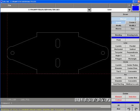
TRUMPF Tops100 V5

Category: CAD/CAM CNC

Article info
  • Views:
  • Author: vipsoft
  • Date: 23-01-2011, 21:38
23-01-2011, 21:38

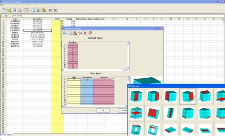
X-cab 2.4.3

Category: CAD/CAM CNC