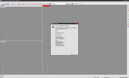
-
Basic capabilities
• Analysis of static influences in accordance with first order and second order theories
• Calculating the structural stability (determining the critical forces and buckling lengths)
• Calculating the natural values (forms and oscillating periods of the structure)
• Generating the seismic load in accordance with various standards (JUS, EC8, SNIP, ...)
• Generating automatically the mesh of finite elements
• Generating automatically the masses in all nodes on the model
• Analysis of influences throughout defined stages of building construction (prefabricated structures, composite structures, etc.)
• Modeling the prefabricated floor structures by orthotropic plates
• Beams and columns with variable cross sections (haunched beams, prismatic columns, laminated wood girders, etc.)
• Modeling the rigid connections in beam nodes (offset beam - diagrams in clear spans)
• Eccentric positioning of beams and columns (true modeling of girders in plates, columns with abrupt change of cross section, etc.)
• Analysis of influences in prestressed structural members (arbitrary cable geometry and calculating the prestressing force loss)
• Foundations on elastic ground
• Assigning the completely arbitrary character and direction of load action
• Analysis of influences due to live load (defining the completely arbitrary pattern and path of live load)
• Generating automatically the load on rotationally symmetric parts of the model due to various natural phenomena: self-weight, snow, pressure, water, earth, wind
• Calculating due to temperature influences and support displacement
• Automatic dimensioning of reinforced concrete (JUS, EUROCODE, SNIP, ACI, DIN, BS, SIA, etc.) structures.
• Automatic dimensioning of steel structures (JUS, EUROCODE, SIA).
• Automatic dimensioning of timber structures (JUS, EUROCODE).
• Creating easily the high quality design documentation with vignette, textual reports and graphic blocks
Graphical Interface
• Defining the arbitrary planes for drawing
• Simultaneous use of planar and space drawing
• Selecting precisely the points in the drawing (dynamic osnap with combined criteria)
• Dynamic zoom and pan. Dynamic rotation of isometric presentation of the model (orbit)
• Manipulating the elements in the drawing (copying, mirror copying, deleting, rotating, complete undo/redo system of restoring the drawings, etc.)
• Generating automatically the vertical elements of the structure
• Generating automatically the rotationally symmetric bodies (sphere, cone, vault, helix)
• Operating with blocks of drawings (saving and entering the arbitrarily selected parts of the model)
• Grouping the arbitrarily selected parts of the model into wholes and deleting the visibility to other parts of the model (only columns, walls, typical floor structures, web members, main girders, etc. visible)
• Visualization of the model (DirectX render, walking through building with camera)
Processing the Calculation Results
• Finding quickly the extreme values of influences in the whole model or only in a certain group of elements (extreme values of axial forces in columns only, etc.) maximal bending moments in plates in typical floor, maximal displacements of walls only, etc.)
• Presentation of results, both in the entire space model and in its certain parts (in selected frame, wall, floor structure, foundations, arbitrarily selected view, etc.)
• Presentation of results in surface elements by isolines and diagrams along an arbitrarily assigned intersection line
• Presentation of influences in linear elements by diagrams and color gradientsPresentation of support reactions with direction and intensity
• Diagrams of stress distribution in composite cross-sections through defined stages of constructing
• Influences in individual parts of composite cross section
• Simultaneous presentation of influences in all columns and walls in one level (insight into distribution of influences due to seismic action on all columns and walls in one floor, redistribution of axial forces due to vertical load onto columns and walls of a given level, etc.)
• Presentation and animation of oscillating forms and deformed model
• Completely automatized dimensioning of reinforced concrete, steel and wood structures (JUS, EUROCOD, SNIP, DIN, etc.)
• Adopting reinforcement in reinforced concrete structures with automatic creating of reinforcement details and export to our program "ArmCad 2005".
Article info
22-01-2014, 15:30
- Views: 4405
- Author: vipsoft
- Date: 22-01-2014, 15:30
Radimpex Tower 6 - Tower 7
Category: CAD/CAM CNC
Go Back
Comments: 0
Dear visitor, Our Softwares not FREE and all work with usb dongle if you interesting buy
Contact ME
Contact ME


