Full Modul
With Orjinal Dongle
Article info
17-06-2013, 15:44
- Views: 3652
- Author: vipsoft
- Date: 17-06-2013, 15:44
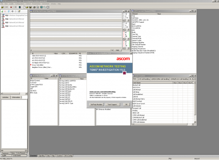
TEMS Investigation 15.0
Category: Telecom Software
Article info
17-06-2013, 15:42
- Views:
- Author: vipsoft
- Date: 17-06-2013, 15:42
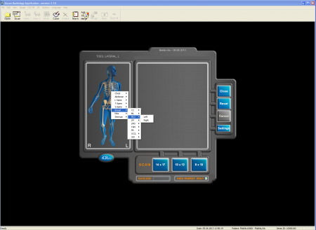
Xscan Radiology Application ICRco
Category: Other Software
Article info
17-06-2013, 15:36
- Views: 5849
- Author: vipsoft
- Date: 17-06-2013, 15:36
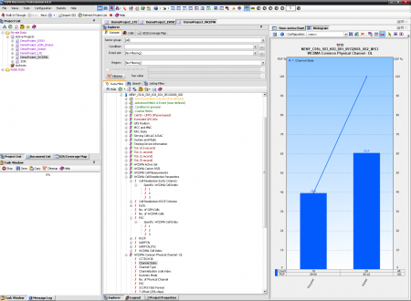
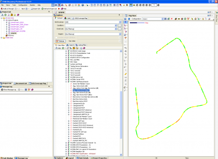
Tems Discovery 4.0.8 - 4.0.9 -.4.0.12
Category: Telecom Software
Article info
17-06-2013, 15:34
- Views:
- Author: vipsoft
- Date: 17-06-2013, 15:34
PLS-CADD - TOWER V12.10
Category: Other Software
PLS-CADD™ (Power Line Systems - Computer Aided Design and Drafting)
PLS-CADD is the most powerful overhead power line design program on the market. PLS-CADD runs under Microsoft Windows and features an easy to use graphical user interface. It integrates all aspects of line design into a single stand-alone program with a simple, logical, consistent interface. No other program can match the sophisticated engineering capabilities available in PLS-CADD. This sophistication and integration leads to more cost-effective designs being produced in only a fraction of the time required by traditional methods. The PLS-CADD solution is so clearly superior to any alternative that it has been adopted by more than 1400 organizations in over 115 countries.
Three Dimensional Engineering Model
Click here for full image
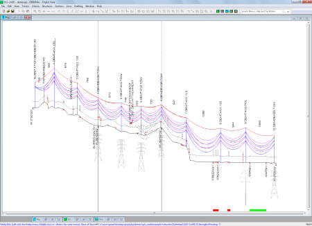
At the heart of PLS-CADD is a sophisticated three-dimensional engineering model. This model includes the terrain, the structures and all the wires. The model can be viewed in a number of different ways: profile views, plan views, plan & profile sheets, 3-D views, staking lists... The PLS-CADD model is much more than just a picture or CAD drawing since PLS-CADD understands the relationship between these elements. When you drag a structure off the current alignment PLS-CADD will generate new profiles and update all affected structure and wire positions. The effects of this structure move will be instantly visible in all views including the plan & profile sheet view. In PLS-CADD you concentrate on designing your line instead of wasting your time drafting.
Terrain Model
Click here for full image PLS-CADD easily adapts to the wide range of technologies used for line surveys including total station instruments, airborne lasers and photogrammetry. It accepts survey data in both the plan and the profile coordinate systems. Survey data can be keyed in, can be digitized using the built in heads-up digitizer, or can be electronically imported from a survey data file. PLS-CADD has a customizable data import routine that can read a wide range of survey data formats.
Superposition of planimetric maps and aerial photographs can be used to better visualize the area around your line. When sufficient data are available PLS-CADD can give you an even better perspective using contour lines, color renderings and even draped aerial photographs.
Altering your line route is easily accomplished by dragging P.I. points with the mouse or by clicking on locations where you want to add or delete P.I. points. Line route changes are instantly reflected in all views.
Engineering Standards & Calculations
PLS-CADD’s engineering functions are very flexible and are easily adapted to conform to your standards. You start by defining the combinations of wind, ice, temperature and safety factors you wish to use. Next, you tell the program which combinations to use for loading trees, for insulator swing checks, for clearance checks, wire tension checks... PLS-CADD will check things your way. You can work in either imperial or metric units and can even switch back and forth between these unit systems. The fact that over 115 countries use PLS-CADD is a testament to its adaptability to a wide range of standards.
Once standards are setup you are only a few mouse clicks away from engineering calculations. Select "Structure/Check" and click on a structure and you are told if you have a structure strength or insulator swing problem. Select "Section/Sag-Tension" and click on a span and you get a sag-tension report. Clearances, loading trees and many other functions are just as easily accessed.
PLS-CADD supports both automatic and manual spotting. With manual spotting you use the mouse to add, delete, edit or move a structure. In automatic spotting the program spots structures for you to obtain the lowest cost design possible subject to your constraints. Automatic spotting often results in designs as much as 10% lower in cost than human generated designs. PLS-CADD gives you the best of both the automatic and the manual spotting worlds: cost and time savings while still maintaining control.
Advanced Sag-Tension
IEEE Std. 738 Static Rating Graph, Click here for information on real-time rating
PLS-CADD has built in sag-tension routines. You can quickly display your line in 3-d for any weather condition complete with insulator swings and wire blowout. Clearances from wires to ground or between phases can also be calculated under any weather conditions. Loading trees, stringing charts, galloping ellipses, IEEE Std. 738 and Cigre Brochure 207 thermal ratings, and offset clipping results are all easily accessed.
PLS-CADD goes beyond ordinary sag-tension programs. Running ACSR conductors at high temperature can cause the aluminum strands to go into compression. Most sag-tension programs do not model this effect and thus underestimate the sags. PLS-CADD can model your line both with and without the compression effect so you can see how severe it is.
Like most line design programs, PLS-CADD uses ruling span approximations in its sag-tension calculations. Unlike these other programs, PLS-CADD can work together with our SAPS multi-span finite element sag-tension program when the ruling span isn't appropriate. When used in this manner PLS-CADD bypasses its built in sag-tension routine and uses SAPS instead. This allows modeling of broken conductors, unbalanced ice, marker balls, and flexible structure scenarios that are incompatible with ruling span approximations. It also allows fixing the length of wire in each span to see the impact of moving structures, inserting structures or cutting out wire in an existing line.
Structure Modeling
Click here for full image Click here for full image PLS-CADD provides several methods for modeling structures. The simplest is the wind & weight span method for which you need only enter values of allowable wind & weight spans, allowable suspension insulator swing angles and the coordinates of the wire attachment points. A far more powerful method of modeling structures is available when using our structure programs. These programs construct a finite element model from some basic input quantities such as pole height, pole class, cross-arm size and guy placement. When such a structure is checked PLS-CADD not only tells you if the structure is adequate but it also displays a color-coded picture showing which parts of the structure are most highly stressed. You have complete flexibility in changing tensions, conductors and loading agendas and can see the results of these changes on structure usage in seconds. Guyed structures, frames and even lattice towers are all easily accommodated. This method is ideal for upgrade studies of existing lines and is far more powerful and accurate than any other alternative.
Material Subsystem
PLS-CADD features a powerful material subsystem for cost estimation and material list generation. Parts data such as stock-number, part description, cost and custom user defined columns can be entered directly into PLS-CADD. Next, assemblies can be created from parts and/or other assemblies. Alternatively, PLS-CADD can extract parts information from an existing company database. All ODBC compliant databases such as Oracle, Access and DB2 are supported and PLS-CADD is easily configured to access existing database schemas.
Parts and assemblies are tied to structures enabling PLS-CADD to estimate the cost of structures or your entire line. A number of different material and staking list reports are available and can be easily exported to spreadsheets or ODBC databases for use in asset management or work order systems.
Drafting
Click here for full image PLS-CADD totally automates plan & profile sheet drafting. Your plan & profile sheets are updated real-time as you make changes to your design. With a few keystrokes these sheets can be plotted to a Windows compatible printer/plotter or they can be imported into your CAD system. Planimetric drawings, aerial photographs, custom drawing borders, title blocks and company logos are all automatically integrated into these drawings. Once again, PLS-CADD adapts to your standards giving you full control over page size, page layout, text size, scales and many other sheet parameters. Customers typically report that PLS-CADD reduces their drafting time by over 95%.
Summary
PLS-CADD addresses the reality that terrain modeling, engineering, spotting, and drafting are not disjoint processes but are all interrelated. By integrating all these functions into a single environment PLS-CADD streamlines the design process. The result is simplicity, flexibility and efficiency not attainable when using a collection of programs from different vendors. PLS-CADD’s engineering features are unsurpassed giving you the state-of-the-art in sag-tension, structural analysis and automatic spotting. From distribution wood poles all the way to 500 kV or higher guyed frames and lattice towers, PLS-CADD has the power and flexibility to do it all. Proven in over 1000 organizations in more than 115 countries, PLS-CADD is the worldwide standard in line design
Article info
17-06-2013, 15:32
- Views:
- Author: vipsoft
- Date: 17-06-2013, 15:32
NC Express V 9.1 - V 11 - V 12
Category: Other Software
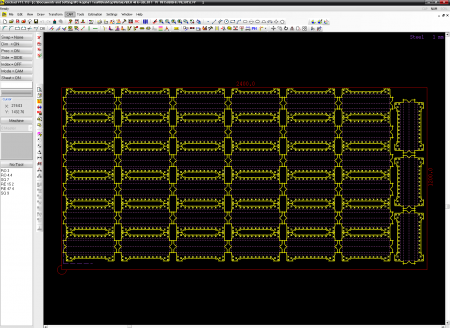
NC Express is a scalable CAD/CAM application that can be use for single part processing or as a fully automatic batch processing software
No matter the production style, NC Express offers support for any programming need for Prima Power lasers & turrets. From importing and unfolding 3D models to processing daily ERP data, NC Express can handle the load.
NC Express offers robust features that are quick and easy to learn: CAD, Nesting, ERP Order Management, Material Management, Tool and Turret Management, Simulation, and Specialized Machine Reporting.
Article info
17-06-2013, 15:31
- Views:
- Author: vipsoft
- Date: 17-06-2013, 15:31
M-Photo 7.1.7
Category: Other Software
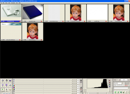
M-Photo Ltd., a privately held company, established in early 2003, develops and sells Production floor management systems for Professional photolabs and print shops using digital printing technology, with the prime emphasis to allow the next generation of digital photography: value added prints, with a focus on photo books.
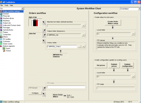
The backend system is sold as a one-time license fee and can be installed on any PC(s) with XP/Vista/Windows 2003/2008 server or Win 7, 32 or 64 bit OS). Customers can create their own contents (product types, graphics) using M-Photo special editors, and include them in the front end tools they create. Orders received at the backend can be loaded automatically, and then, the images included in the order can be color corrected independently of their appearance in the page composition, using M-Photo’s color correction tool (similar to Photoshop quality but able to correct multiple images simultaneously) or via M-Photo’s integration framework with External auto enhancement tools like Perfectly clear lab software or Indigo’s (HIPES). Thereafter, the system renders the final pages and send them to a large variety of output devices (photo printers, inject printers and Digital printers) as JPEG/TIFF files or as PDF files placed at the DFE’s hot folder/virtual printer. M-Photo can also send output to the various DFE controllers (Xerox DocUSP, EFI, Creo or Indigo’s HP SmartStream Production Pro Print Server) using the respective JDF protocol.
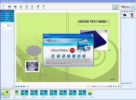
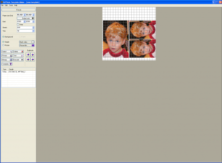
The front end tools include: Order maker (for regular print orders offered by photolabs), Order maker Pro (for school/sports photography, including variable data) and Album Maker (Runs on PC/Windows and MAC/MAC OS, targeted for the consumer market segment and the pro photographers), for the creation of photobooks, photo albums, calendars, greeting cards, posters, and more.
The front end tools could be created in multiple versions, and accordingly could be distributed by corresponding business affiliates. Each version can be unique in look, product types, offering price and graphics content, as well as different in administration (integrated with a different on-line payment system, etc.).
The M-Photo product line has already been adapted to over 25 languages. The product is sold world-wide directly or via distributors. Currently, M-Photo sold over 250 systems to customers located in 30 countries in North America, South America, Europe, Middle East and Africa, South Asia and the Asia Pacific.
Article info
17-06-2013, 15:25
- Views:
- Author: vipsoft
- Date: 17-06-2013, 15:25
Metrolog XG V10
Category: CAD/CAM CNC
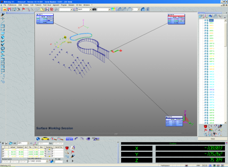
Metrolog XG for Leica – Developed by Metrologic Group of Europe – The global 3D inspection software is a standard for measuring applications in automotive, aerospace and the general precision industry.
Metrolog XG for Leica interfaces to the Leica Geosystems Laser Trackers and the "Walk-Around" Leica T-Probe. In addition, more than 50 interfaces for CMMs and PCMMs are available. The graphical visualization provides direct interfaces for virtual any neutral and native CAD format. A powerful feature-based measurement tool, a complete GD&T engine, customizable reporting and a simple and fast programming language, support and simplify your sophisticated assembly and inspection processes.
Article info
17-06-2013, 15:23
- Views:
- Author: vipsoft
- Date: 17-06-2013, 15:23
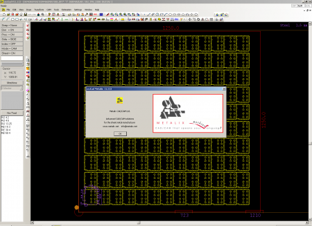
Metalix CNCKad V11 2011
Category: CAD/CAM CNC
The Complete CAD/CAM Solution
cncKad is the only software which has integrated CAD/CAM capabilities in the same module: Geometry, Dimensions and Technology (Punching/Cutting) are completely associative - when the Geometry is modified, Dimensions and Technology are automatically updated!
cncKad features 2D & 3D design, Automatic Nesting, NC Generation, Graphic Simulation and Machine Comunication.
Request a Free Trial Instalation of cncKad Software Customer Services Download a PDF with cncKad's New Features
Article info
17-06-2013, 15:20
- Views:
- Author: vipsoft
- Date: 17-06-2013, 15:20
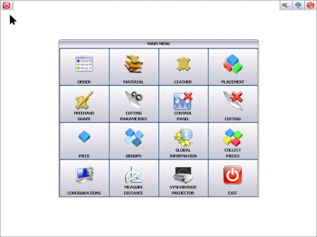
Teseo Machina MDE Dos Software All Version
Category: Shoe CAD
Article info
17-06-2013, 15:18
- Views: 4449
- Author: vipsoft
- Date: 17-06-2013, 15:18
GPS.Opt 7.55
Category: Other Software
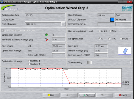
Focusing on wastage results alone reserves GPS.opt the top position in the industry’s software solutions. GPS.opt also allows a seamless integration into the production control software and the associated benefits of using a range of perfect planning tools to layout the cutting schedule. This secures a competitive edge for your company.
In combination with TSO – the first true shape optimizer, GPS.opt increases the potential to save material and therefore money.
With GPS.opt you can decide to use A-racks or harp cars to stack the glass after cutting. The stacking method makes no difference to the system. The program optimizes the space required on the racks taking into account the production sequence and packing requirements.
The stock plate editor allows the operator to modify the optimization and add new sizes manually or insert remakes to avoid wasteful remnant sheets. Normal optimizers surround shapes with a rectangle to allow breakout, but this increases the wastage enormously. TSO however integrates the shapes together, which reduces the waste signifi cantly. The degree of nesting can be selected using parameters in GPS.opt, but the system automatically generates help cuts to aid the breakout of complex shapes.
"DXF, CAD, CNC”, these technical words are part of the GPS.opt vocabulary. Using these standard interfaces GPS.opt can receive geometric code and convert it into control code to directly run cutting tables, glass loading systems.
- See more at: http://www.lisec.com/en/Automation/Production-Management/GPS.opt#description
Previous
Next


